
|
MICROSTEPPING |
MICROSTEPPING is a technique for increase the angular resolution of the motor by electrical means.
A normal hybrid type stepper motor has typically 200 steps per revoluition and when pulsed in the correct sequence will rotate step by step. You can remove the power and it will stay there. In fact when it is unpowered (and unconnected electrically), you can feel the steps when you rotate the armature by hand. A motor like this is not much good for astronomy unless it has a gearbox fitted before it drive the wormwheel.
Driving a motor at 15 steps per second to follow the stars means the step size is 1 arcsecond and the total reduction ratio must be 1 to 6,480 revolutions of the motor. [There are 3600 arc seconds in 1 degree, 360 degrees in a circle and there are 200 steps in the motor revolution]. So for example you would achieve this on a 144:1 worm ratio with a gearbox of 45:1. But unless you have complicated electronics you will only get the motor working at a maximum speed of three revs per second before it stalls, therefore it is flat out at 40x sidereal rate. The dynamic range of the system is 40:1
If you can put a partial current in each phase of the motor and control it properly then you can place the armature at any rotation point between the poles of successive steps. This means you can stop it anywhere. You would typically hold it in this position by a Pulse Width Modulation (PWM) technique. AWR uses this method to provide 64 equally spaced microsteps between the step to step position. If the current is removed, the armature would jump to the nearest pole, so one drawback is you have to keep the motor permanently powered. Let us see what happens to the example.
The motor mow has 200 x 64 = 12,800 steps per revolution. From 15 steps per second to 3 revs per second is now a dynamic range of 2560:1 (64 times bigger than before). Effectively we have put in an electrical gearbox of 64:1 ratio so we do not need the gearbox we had before, in fact we can couple the motor directly to the slow motion shaft if we wanted to. Here is the second drawback - with a gearbox we increase the motor torque by the gearbox ratio (discounting the efficiency for the moment) so if we were to directly couple the motor we would need a 64x more powerful motor to rotate the worm shaft with the same power as before. In practise we use small gearbox ratios 2:1 up to 5:1 to get our torque.
Using microsteps we can optimise the step rate, delivered power and the slew rate by selecting the right motor size from our catalogue. A totally programmable drivebox is required which is what AWR has with its Microstep range of Driveboxes.
FOR THE TECHNICAL
The microstepping technique has to be tested thoroughly to make sure the angle increment at each microstep is uniform, on and off load. To do this you need to set up a motor which can be loaded with a known torque and use a light beam pointer to mark individual step movements. At 64 microsteps on our 200 step per rev motor, one microstep corresponds to 1.69 arc minutes, so over a 10 metre path the spot will move 4.9mm in one microstep. AWR have done this.
The low power translation table offered by AWR (4042BV7) has been characterised and offers constant torque irrespective of step position as shown below. We have compensated for the pole pull-in mechanical torque to give a more even translation.
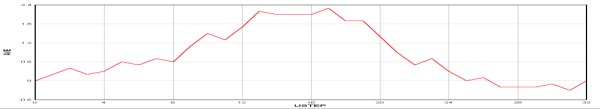
Now another bit of theory. For the motor to deliver some power there must be an angle between the magnetic and electric lines of force (otherwise there is no torque), and the more power required the bigger this angle is. This is a linear relationship up until the holding torque, then the motor cannot hold the load and it slips or stalls. So to achieve a constant rate of rotation with a constant step rate you need a CONSTANT LOAD TORQUE. You also need a CONSTANT MOTOR TORQUE available from the microstepping method and electronics. If BOTH of these are not so, you will end up with periodic error having a period equal to the step to step time. This point is important so annual maintenance is required to bring the drive back up to its expected performance. Note this error is going to be relatively small as the period is normally less than 2 seconds!! The above graph shows that this is nearly achieved by the AWR equipment. It is motor specific so each motor type should be characterised to get the best translation table, but that greatly increases costs.
| © 1997-2008 AWR Technology | 01304 365918 | www.awrtech.co.uk |
|---|