
|
AWR TECHNOLOGY - Sept 2008www.awrtech.co.uk |
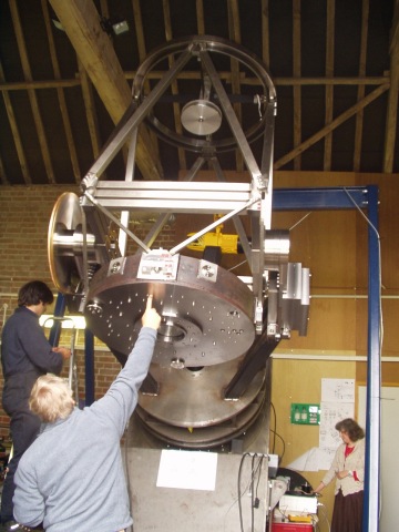
AWR have been busy making a drive box / electronics system / mirror support system for this new telescope being built at Norfolk Optics. This is the first of a new design of what we hope to be the first in a range with design capability at least up to 2 metres for those with a big enough purse. The total weight of the 32 inch is 2 tonnes.The standard AWR Intelligent Drive System controls the mount although it has been ruggedised and adapted to be fit for purpose. The telescope is destined for a site at 8000 ft.
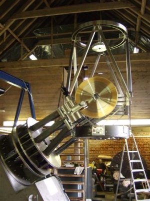
We are using SANYO-DENKI frame size 34 motors at 3 to 4 amps drive current per phase to generate approx 2.5Nm constant torque through the microstep cycle. The worm and wheel and motor support stage weighs in about 140kg and so there is a balance weight of this value on the other fork. The worm assemblies are sprung loaded. During testing the DEC axis requires 50Nm to turn with the motor stage uncoupled. The POLAR axis takes 200Nm under the same circumstances.
The telescope has external encoders from Heidenhain with a friction drive reduction of 10x to give under 10 arcseconds resolutiion.
There will also be a closed loop pneumatic load cell mirror support system, similar to that used on the William Herschel Telescope but now available to amateurs. Control electronics are being developed by ourselves.
Additional computer control through LINUX based Xephem / Talon or Windows based 'The Sky' / ASCOM or ACP will also be possible.
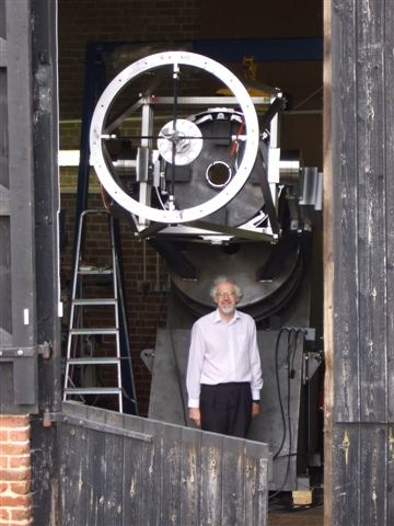
| Mirror cell and DEC worm assy | End on with Alan Buckman |
|---|---|
 |
 |
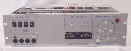
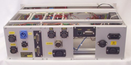
| The DEC 0.5m Worm and wheel | Views of Drive Box |
 |
 |
 |
We have been struggling for some time to get a working algorithm. The reference sources show you how to compute the instantaneous tracking rates which is all very well until you try and implement it. This works by taking the current coordinate (whatever that is) computing the rates which you then implement. However this takes time and there are lags in the system meaning the tracking drifts. Not only that but the ertracking error can blow up at various parts in the sky. This is not sensible. Each coordinate in the AWR system is only as accurate as the resolution, one encoder count, which can be 20 arc second in low RATIO systems. The coordinates (and object) will still drift even if you had 1 arc second encoders.
What you meed to keep in mind is the required target coordinate called the 'bullseye' and aim for it at each correction so the scope drives to it at the end of the correction interval. It does not matter then about the encoder resolution Given a quantised error in the input of 1 count you are at maximum going to be 1 encoder count out at the end of the interval. If it overshoots, it will come back in the next interval. But the important point is that the microstep resolution (64 steps per encoder count) means the tracking is smooth on both axes so your object is going to stay on target with a very long period wobble. Even in places where the telescope can not move as fast as desired (the zenith), it will eventually catch up on the other side of the meridian and re-acquire the object.
The implementation is a different compilation for the Intelligent Handset code, and so is a firmware exchange. We have yet to complete changing the bullseye when the handset manual buttons are used but it is a start....
In CCD photography with autoguiders used to increase the apparant resolution you stack photos with your autoguider on. But the autoguider tends to correct the drive to keep it within 0.2 pixels of the camera. What you really need to do is take a group of exposures, then move the telescope 5 arc seconds or so, then take another group of exposures. The image has landed on a different group of pixels and the autoguider profile will be slightly different This is essentially an 'optical dithering technique' for digital cameras. Try it! The SEEKER is suitable for all scopes with an autoguider input.