|
ACTIVE MIRROR SUPPORT |
BENEFITS
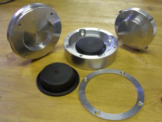
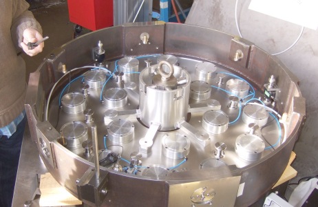
| MAJOR COMPONENTS The photo gives a peek into the mirror cell before the mirror is loaded in. It is very busy but contains very different equipment to traditional bars and lever and pad supports. This is an 18 point suspension system.
|
|
PERFORMANCE
Part of the AWR development is the provision of serial monitoring using our PC programme called WINDISP (freely available by download). This in its full form allows access to all parts of the data measurement with logging of all the variables. An amount of commissioning is involved in setting up the pressurising envelope parameters by using the DEBUG mode of this programme and the Mirror servo box. Quick stabilisation of the mirror without oscillation is required. We achieved around 12 seconds with a preliminary set of paameters.
The loadcell is extremely sensitive and full scale is achieved by a little over 1 turn of the collimation screw. However initial setup is extremely simple and quick. The full height travel of the diaphragms is about 2mm, so each sector is pumped up to 1mm raise and then the collimation screw adjusted until the loadcell value reads 5 Newtons. That is it! When active, the largest normal excursions we have seen were +/-0.15 Newtons on the loadcell corresponding to +/- 15 grams force. It is generally much better than this, about +/- 3 grams force.
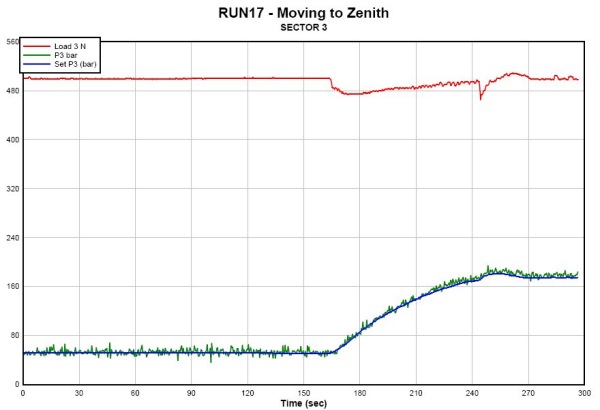
This graph shows the three parametrs for one sector only - the loadcell, request pressure and measured pressure. It is a time span covering stability at an altitude of 20 degrees, slewing up to the zenith at 0.8 degrees per second, then regaining stability when the scope has stopped. The other two sectors are different. It all depends on the centre of gravity of the mirror, the symmetricallity of the implementation, and indeed collimation adjustments. Note the pressure is very much reduced when the altitude is 20 degrees, yet the mirror is still at the same working height because the load cell value is constant. The mirror at altitude is mostly supported by the radial support arms, with very little resting backwards on the diaphragms.
SUPPLY OF SYSTEMS
AWR Technology and its partners can supply complete kits of parts to make this happen. There is a sophistocated gas system with valves, pressure switches and reservoir using 6mm push fit fittings, the servovalves - we use Asco Joucomatic valves - and load cells. The amplifiers, measurements and electronics control system has been developed by AWR and supplied in a box that bolts onto the rear of the mirror cell. Other mechanical parts have to be made are the Bellofram rolling diaphragm pressure actuators and the axial definers.
We can also supply a license to make one set of mechanical parts, with supply of one electronics box and the difficult bits. Please contact either Alan Buckman (AWR) or Brian Mack (Mack Consultants) for further information.
| AWR HOME PAGE | PRICING |
© 2009 AWR Technology