
IDS CALIBRATIONS & ACCURACY
www.awrtech.co.uk
|
IDS CALIBRATIONS & ACCURACYwww.awrtech.co.uk |
|---|
The overall concept of the IDS is to take out variabilities and deficiencies in all types of telescope by calibrations. Thus it can be fitted to a large variety of mounts and drive constructions.
Further background information can befound in our articles.
ONCE OFF - FACTORY - SETUPS
These are the entries for RATIO, SLEW, ACCEL, MSTEPS, to match together
the telescope reduction ratios, the type of drive box and the basic IH
calibrations. If you have a friction drive then the RATIO values are going to
be subject to inaccuracies and will have to be altered to get the star tracking
rate correct. At the end of the day the telescope should track the stars for
long periods without drift and when it is moved by 30 degrees then the display
should match the new value precisely. The best method if you need to adjust the RATIOs is to alter the value by 1% and take note of what happens to the star following. The value entered for RATIO is the number of encoder counts per circle. (One encoder count is one full step of the motor). If the mount is not tracking fast enough then the motor needs to speed up and so there are more encoder counts per day so increase the value in RATIO. When the reduction drive is totally by gears and worm wheel then the RATIO is known exactly and should not be touched.
Only when the RATIOs are correct will the GOTO performance be realised. You can TEST if you have the correct values by checking that when you slew the telescope through a full circle, the coordinate display also goes through a full circle. The DEC output does not have the sidereal rate superimposed so on most mounts you can also check the RA axis by operating with the DEC motor lead plugged into the RA motor.
At the telescope the BACKLASH values should be experimented with. In an ideal setup there will be a small amount of backlash (perhaps 20 arc seconds) in both axes and they remain constant over different parts of the worm wheels. With some suppliers of worm wheels there may be more backlash at one point and a minimum 180 degrees away. In the IH the RA BACKLASH is done when the motor reverses (CENTRE speed or higher) as a high speed blip at the start of the movement and a high speed blip when you take your finger off the button. So the RA tracking then continues properly without any dead spots. The DEC BACKLASH performs a high speed blip at the start of the movement when the movement is in the opposite direction to the previous movement. This is especially important if CCD autoguiders are used and DEC control is required. The correct software must be in both units for backlash to be operational - this is V1.3 IH and V0.59 for the drive box (or later versions).
The pointing accuracy is affected by many issues and these are typically:
|
 |
|
|
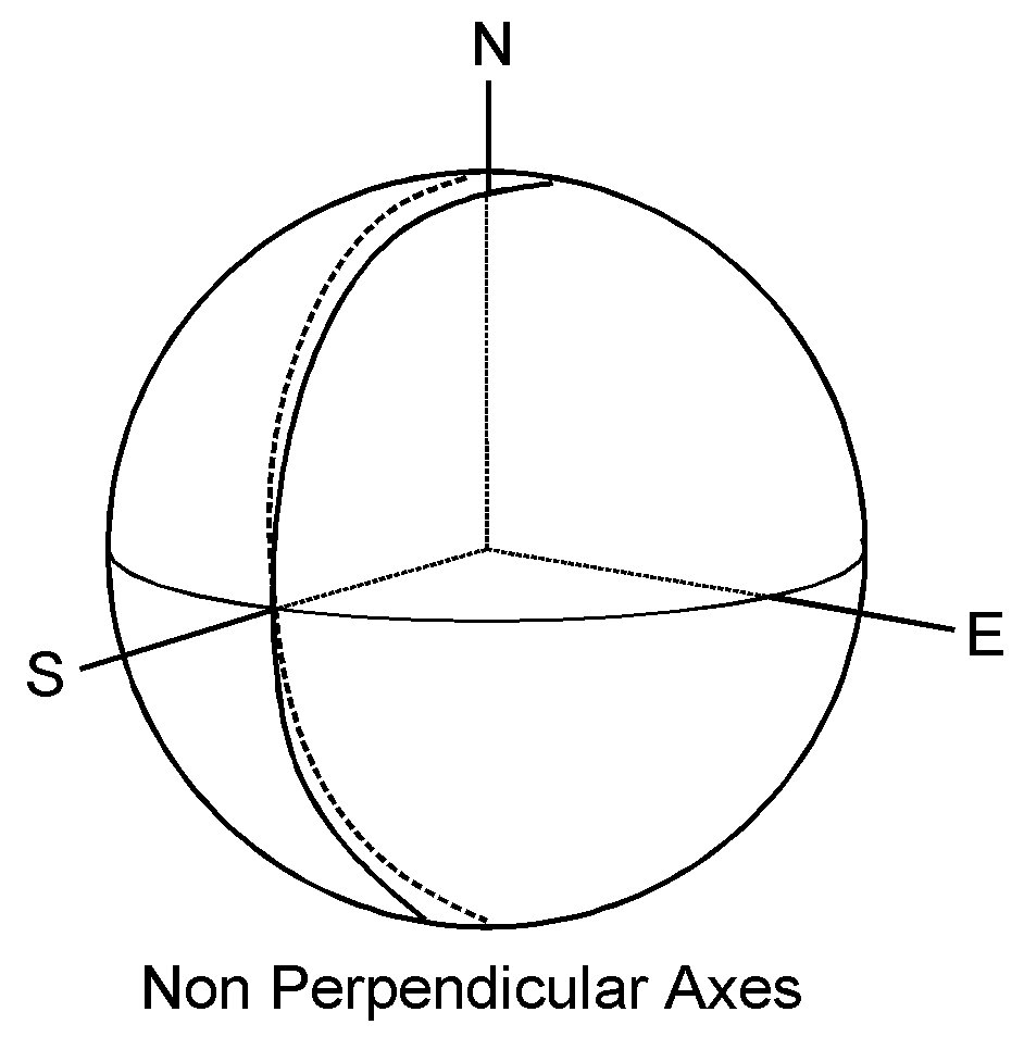
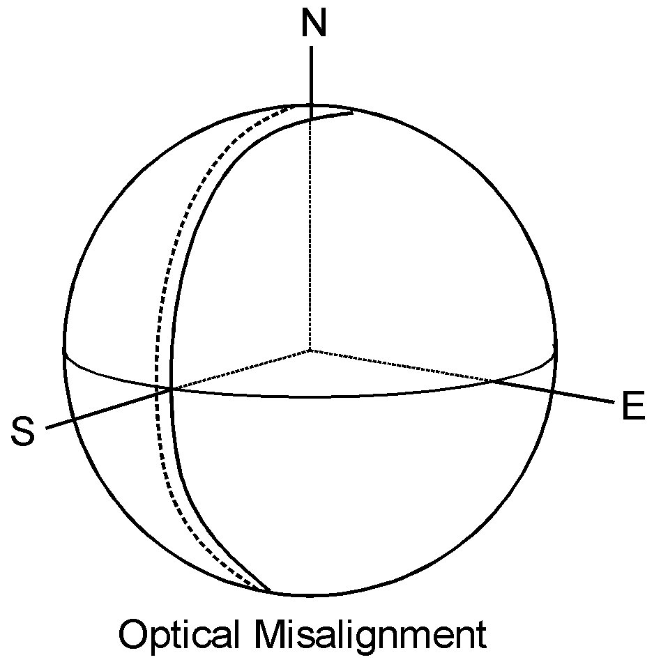
The analysis holds for FORK and GEM type mounts. So if you reverse the tube (FLIP or MREV) at the meridian at DEC = 0 degrees using the CAL3 procedure then you will find the OPTICAL MIS_ALIGNMENT ERROR. Repeat the flip at high value of DEC then you can get the NON-PERPENDICULAR or CONE ERROR. It is not possible with a single third calibration point to adjust for both these two errors as they are both present.
Optical mis-alignment is the optical axis of the telescope not being parallel to the RA mechanical axis. The procedure for removing this is to first correctly collimate the optical tube (using a laser adapter collimation tool), and make it symmetrical to the centre of the optical tube assembly if you can. Then you need to determine the residual error when you flip the scope at DEC = 0 degrees and pack the tube assembly until this error disappears. This is exactly the same procedure as required when aligning the optical axis of a POLARSCOPE to the RA mechanical axis.
Only then can you get the cone error by carrying out CAL3 procedure with a star at high declination value.
Pointing accuracy can be improved in the presence of these errors by using TPOINT or MAXPOINT but these require coordinates to be sent from 20 or so stars all over the sky to as high a precision as possible to get an accurate result. RETURN TO TOP
An important point is that you must have a mechanical method of providing fine adjustments to the position of the AZIMUTH and ELEVATION of the pole. If you have such adjustments you will need to work out how far you need to move the adjustment screw to get 1 degree of adjustment. It may only be 100 degrees of turn of the screw but this may be enough. You should aim to compensate for an error as small as 0.1 degrees as a result of the two star calibration for good alignment.
The DRIFT METHOD of polar alignment will not produce the accuracies required for good GOTO accuracy, but you can read about!
GOTO performance can be poor due to several reasons. The accuracy of the performance is described in the above sections with all sorts of reasons why the target is not dead centre after doing a GOTO.
For ROBOTIC applications you may not want the motor to change direction during the GOTO process. The GOTO algorithm has been optimised for version 1.6 and onwards but it is still possible for the slew down process to overshoot as follows. The whole process is modelled within the handset to know when the SLEW rate should be stopped, then it decelerates to the MOVE speed to the next trigger point then slows to the CENTRE rate to creep up to the position. However there are delays at each step and the actual amount of "button presss" is not entirely predictable.
Now let us consider the acceleration time to reach the MOVE speed. The default setting for MOVE is 32x sidereal (0.133 degrees per second). If SLEW speed is set at 0.5 degrees per second and it takes 10 seconds to get to the slew speed then it will take 2.67 seconds to get to MOVE speed. This is beyond the allowance made for the GOTO routine so it will overshoot. It is possible to change these circumstances by speeding up the acceleration so you go from rest to full speed in 5 seconds and reduce the MOVE rate to 20x then it only takes 0.417 seconds to get to MOVE speed. This should be handled properly in the GOTO performance without overshoot.
MREV is MERIDIAN TUBE REVERSAL which is an essential function for GERMAN EQUATORIAL MOUNTS amongst others. The telescope tube must be reversed if you want to continue tracking an object from the Eastern hemisphere to the Western hemisphere. The IDS provides an automatic function to do this by pressing a button in the GOTO menu. The telescope however must be close emough to the central meridian before it will accept it as a valid operation. The limits are 30 minutes before the meridian or any time after the meridian. This also applies to crossing the meridian below the POLE.
Set MREV to 'YES' (FACTORY-USTEP-MREV) to use this function. NB The telescope must be capable of performing this procedure!
It has another use in that it allows you to measure the PERPENDICULAR error (CONE error) of the two axes. If you calibrate on a star near the central meridian and 0 degrees DEC then do MREV. The amount the star is out after doing an MREV is the amount of the perpendicular error. Version 1.3 software and older require the telescope axes to be exactly perpendicular, so it will be necessary to put a wedge under the tube to get this right. Doing another MREV will confirm that it is correct. It can be done on the same star reversing from one side to the other until you are happy.
For FORK MOUNTS setting MREV to 'NO' will not do Meridian reversals but it may still go over the pole. In this instance there is another setting for MAXDEC - the Maximum Declination the scope will move to. This setting is available from V1.5 and onwards of the IH software. If it is set at 90 degrees then it will allow a movement over the pole. If MAXDEC is set less than 90 degrees then there will NEVER be any excursions over the pole.
© 2006 AWR Technology