
|
MISC TOPICS |
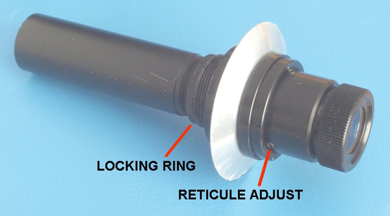
If you have an equatorial mount with an in-built Polarscope (or can add one) then polar alignment can be achieved very quickly. This is very good on portable mounts! It is a small telescope with a large field of view (5 degrees or so), with a reticule containing various symbols. It is arranged to point up to the pole. You must do an inital setup (done once) then it is ready for use.
A small Polarscope can be purchased as an accessory. It fits the following mounts which all have the same fitting (M18 x 1mm): Vixen GP, GP-DX, Synta EQ5, HEQ5. In use the eyepiece should have the reticule sharply in focus (with glasses if you wear them) and stars should also be sharply in focus. If one of these tests fails then you need to carry out the INSTALL process.
INSTALLING IN THE MOUNT
Installation and adjustment should only be done once but adjustments to its set-up will need done if either the graticule or the stars are not sharply in focus or the crosshair is not coincident with the telescope rotation axis. It should stay in adjustment unless it is knocked! The steps for adjustment are
Re-Positioning the Reticule (INSTALL)
The reticule is held in position by three Allen screws. To move it laterally so that the central cross hair changes position then you must unscrew one Allen screw and do up the others. I suggest this is done 1/4 of a turn at one time otherwise the reticule could become dislodged from the three point mounting and will then rattle in front of the eyepiece. If this happens then remove the eyepiece. Do not touch the surface of the reticule with fingers. The grease will create extra unwanted features! You can then re-position the reticule back in the Allen screws and replace the eyepiece. This procedure should be done in daylight.
The reticule is mounted on a metal ring against which the Allen bolts press against. If the reticule is loose, there is nothing to stop it from tilting towards the eyepiece if you are looking upwards. The reticule should be positionned against the backstop which is away from the eyepiece, so point it downwards with the screws loose.
|
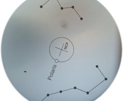
USING THE POLARSCOPE Northern hemisphere Polarscopes should have a few constellations picked out and a circle offset from the central cross hair in which Polaris must be placed. (See picture). But first you need to rotate the whole RA axis until the constellation pattern is in the same orientation as in the sky. It must be an exact match or as near as you can get it - this puts the Polaris hole in the correct position! I suggest you do this with the telescope OFF the mount as the RA axis can be at a completely unusable orientation. Having got the correct orientation of the RA axis then you can put Polaris into the circle by using the mount adjustments for altitude and azimuth of the pole. So it is necessary for you to see the reticule and all the symbols when using it. You can only do this in dusk (provided you can see Polaris) or you need to shine a light onto the Polarscope far end or build one in. (See the AWR Illuminator add-on product). |
|
When Polaris has been positionned correctly, the scope and counterweight can be mounted and the position of Polaris checked again. This ensures that the mount has not moved. You can check the setting by drawing an extended line through the crosshair and Polaris which should come very close to Kochab (see below).
Southern Hemisphere Polarscopes have a different set of constellations to match but no bright star close to the pole so the accuracy achievable is not so great. Otherwise the procedure is the same as for Northern hemisphere observers.
If the mount has a bubble level device then you can accurately set up the altitude adjustment of the polar axis and you can reproduce this fairly accurately next time you set up the mount, but the azimuth adjustment will still be necessary. You can of course paint spots on the ground for the tripod legs and get fairly close. Absolute accuracy is only necessary if you need to perform GOTO operations, or take long exposure astrophotos.
A final note: due to 'precession' the position of the pole relative to the reticule alters by about 1 arc-minute each year and so the spot to aim for will change appreciably over the lifetime of use of the reticule. Using Kochab (Beta UMi) it is possible to adjust the angle of Polaris so that the crosshair to Polaris circle line extended goes within a short distance of Kochab. The RA coordinate of Kochab (14h 51m) is substantially constant over this period. So the table gives the nearest distance of the 'extended line' to Kochab.
| -- POLARIS -- | -- Short distance -- | ||
|---|---|---|---|
| YEAR | RA | NPD | degrees |
| 1990 | 2h 21m | 47' | +2.1 |
| 2000 | 2h 32m | 44' | +1.3 |
| 2010 | 2h 44m | 41' | +0.5 |
| 2020 | 2h 56m | 39' | -0.3 |
The effect of polar axis misalignment is to cause a drift in declination and some field rotation. It masks errors from other sources making it very difficult to disentangle them. For accurate work it is essential to align the polar axis as well as you can, checking the adjustments after setting up. The alignment error (rotation axis compared with Earth's rotation axis) is resolved into two components - an error in azimuth and an error in altitude. An easy method for assessing the accuracy of the alignment is to carry out drift examination when the telescope is pointing in various parts of the sky. It helps to have cross hairs on a high power eyepiece as drift can be detected quicker. The cross hairs should be aligned with one axis in the RA movement direction. This can be a fairly slow procedure depending on how accurate you want the setting. You do not need to have the RA driven.
- Azimuth error.
This causes the declination drift to be most pronounced on the meridian. If the
azimuth error is to the East then the star will drift south both sides of the meridian
and the corrective action is to move the pole azimuth to the West by rotating the
mounting anticlockwise (northern hemisphere observers). At exactly
6 hours Hour Angle the polar azimuth error has NO EFFECT.
- Altitude error There is no drift on the meridian but declination drift is most pronounced with a star in the east or west (at an Hour Angle of 6 hours). The effect is symmetrical about the meridian. If a star in the east drifts north then the rotation axis is too high. At the meridian the polar altitude error has NO EFFECT.
| Drift table for Northern Hemisphere observers: | |||
|---|---|---|---|
| Star in | Drift Dir | Polar Axis Error | Corrective Action |
| east | north | too high | lower pole |
| west | south | too high | lower pole |
| east | south | too low | raise pole |
| west | north | too low | raise pole |
| south | south | too far east | rotate anticlockwise |
| south | north | too far west | rotate clockwise |
Methods of polar axis alignment with and without setting circles are given in "Norton's Star Atlas & Reference Handbook".
The DRIFT METHOD will get your RA axis exactly in alignment but it is a long procedure. However it should be done for stars above 30 degrees altitude so refraction effects do not upset the adjustments. The other point is that it is quite difficult to quantify the movements and the amount of polar axis adjustment so you need to take note of what you do so that you can undo it exactly if you went the wrong way. Here it helps to have screw adjustments for the altitude and azimuth adjustments of the polar axle.
WHAT IS IT
TORQUE is a measure of the turning force when a tangential force is applied to a shaft causing it to rotate. A telescope usually requires a huge torque to rotate which is why there are huge gear reductions to bring the required turning force down to manageable levels from a motor. This section is all about its measurement but typically it would be applied to the slow motion axle (the one with the worm on) to make sure you know the torque requirement from the motor. The motor must be more powerful than the load else it will stall. When you check the torque requirement do remember to uncouple the motor so that you are only measuring the torque to turn the telescope. When you are checking, please check with the telescope in quite a few orientations, note down the minimum and the maximum measurements. If you find there are tight spots requiring more torque then you need to carry out maintenance as you will get drive following problems through these tight spots.
It is measured in NEWTON-METRE (SI units) or pound-foot force (in older units). All but the very smallest gearboxes have an output maximum torque capability of 1 Newton-metre or more. Motor outputs are much smaller and usually given in Newton-centimetres.
The clues to its calculation lie in the units used. Force is MASS x ACCELERATION so if we use a weight in the Earths gravitational field then we can calculate the force and we can measure the distance to the rotational axis. We take the acceleration as gravity g = 9.8 metres per second per second Now we need to be clear what a tangential force is. This is the force in the direction at right angles to the measurement of the distance to the centre of the shaft.
METHOD 1 - HANGING WEIGHT
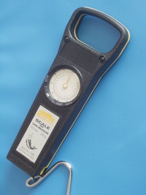
So if we wrap a string around a horizontal shaft then hang a weight on the end of the string, the string and weight will hang downwards and the distance to the centre of the rotation is the horizontal distance to the centre of the shaft (or its radius). You have to add weight until the axle just starts to turn. It is much more convenient to use a Fisherman's Spring Balance instead of the weight. Make sure you pull on the string at right angles to the axle.
It is important to make sure the torque required is that just to turn the shaft, Check that it is the same if the shaft is rotated in the other direction, and check that the requirement is even without any tight spots. This causes problems for motors, stalling at a much slower slew speed. The STATIC TORQUE is that required to turn the axle from rest. The DYNAMIC TORQUE is that required to keep the axle rotating at a constant speed.
TYPICAL RESULT
A 5kg weight is just enough to turn a horizontal 2.4cm diameter shaft. So the torque is [weight x 'g' x radius]
|
METHOD 2 - USING A SPRING BALANCE An alternative method to a hanging weight is a Fisherman's Spring Balance. (We can supply a suitable item for £7.00 including post). You still need to attach a string round the shaft you want to measure, but now just pull the spring balance (attached to the string) and take the reading. This will give a number in kg which can be converted to force by multiplying by gravity. You then get the torque by multiplying by the radius of the shaft. When you pull the spring balance keep the string at right angles to the shaft. Calculate the torque using the "weight" read off the scale, as per the example above.
EQUIVALENTS AWR can supply you with a spring balance. |
|
We have accumulated a lot of knowledge on worms and their fitting and operation. It is one of the important parts of the drive, the mechanical mounting and ajustment is critical to getting good following and low backlash. This is the place where errors get totally magnified as one rotation of the worm can be 10 minutes and any play in the worms mechanical position gives a big effect. The overriding requirement is that the worm rotation must be completely smooth with no tight spots or unwanted movements. Owners of a well known commercial SCT take note!
THE WORM
The worm tooth should not bottom in the wheel. The area of contact should be on the sides of the teeth, so the tooth profile should be truncated with a flat top. Machined teeth can be trapezoidal in cross section and if so would have a pressure angle of about 20 degrees. The correct mating position with the matching wheel is both sides of the tooth in contact so the backlash adjustment must wind the worm into the wheel until the teeth are properly in contact. Springing of the worm into the wheel is a very good idea!
THE SLOW MOTION AXLE (THE WORM SHAFT)
This should be round and straight! It must also not bend and so the cross section should be commensurate with the forces to hand in the design. It should be held in a substantial housing, usually with roller bearings.
THE WORMWHEEL
Also called the CROWN WHEEL. It should be hobbed at the same radius as the worm to allow for a large amount of contact of each tooth of the worm in the wheel. If the wheel is just cross cut without any hobbing then the point of contact with the worm is very small indeed. A properly hobbed wheel has a contact area of upto four teeth times the width of the crown wheel. This of course is much better because a) it can take greater loads due to the much larger contact area and tracking imperfections will tend to be averaged out.
Some crown wheels have lost centres and are bolted onto flanges (as in the Alter D6). This allows them to be set up properly after the flanges have been secured properly. The adjustment involves using a precision ball depth gauge and requires to be done very carefully to get it right. The adjustment face must then be secured so it will not slide later on.
WORM HOUSING BRACKET
The function of this is to hold the worm in place via the roller bearings. It must also allow for the bearings to be captive, and the distance between the two adjustable to get rid of endfloat. They usually bear down onto shoulders on the worm shaft. The motor is also fixed to the worm bracket, and so this assembly can weigh 2kg for the largest motor.
BRACKET SUPPORTS & ADJUSTMENTS
The worm bracket support must hold the worm rigid with no twisting in relation to the wheel. Material no thinner than 6mm Aluminium is essential to meet this requirement. An adjustment should allow for
(1) Placing the worm in the same plane as the wheel.
(2) Vertical adjust across the face of the wheel teeth, to allow the worm to bed properly in the teeth.
(3) Inward adjustment to nestle the teeth closely together.
(4) End float adjustment on the slow motion axle for reducing backlash.
There is only one position for the worm!
FORCES INVOLVED
A 250kg tube assembly required 2.1kg of force at 0.71m to turn it with the DEC unclamped. It was the same being pulled up or down when using the spring balance. This torque is 14.6Nm. At other positions in the sky this went up to 5.0kg or 35Nm.
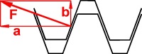
The wormwheel is 0.295m diameter with 287 teeth made in phosphor bronze. So at the edge of this wheel the 35Nm maximum torque is a force of 238 Newtons to rotate it (tangentially to the wormwheel edge and force 'a' in the diagram below). Note this force also bears in the opposite direction on the endfloat adjustment of the slow motion axle. This is a HUGE force.
Now we need to calculate the maximum spring force required to keep the teeth engaged and also the torque required to rotate the slow motion axle.
Maximum Spring Force. This is a standard inclined plane problem as the simplified diagram of the tooth contact region shows. The wedge angle is normally 20 degrees for machine cut tooth profile (as in Beacon Hill Telescope's worms). So the spring force is to work against the outward force 'b' in the diagram and this is 87 Newtons. In practise it must be much higher than this to keep the teeth well meshed and it must also rotate the tube in a static situation if the teeth are partly unmeshed.
Breaking Force on the tooth. Big force 'F' is 253 Newtons which must be below the tooth shear point!
Torque required to turn the Worm. Using the 35Nm torque and the reduction ratio of 287 with an efficiency of 0.1 requires a torque of 1.2Nm The actual torque will also be this plus extra to drive against the spring force, perhaps double what we have calculated. This is maneagable by our large MOTOR/210. The coefficient of friction between Phosphor-Bronze and Steel (=0.35) plays a part in the efficiency figure.
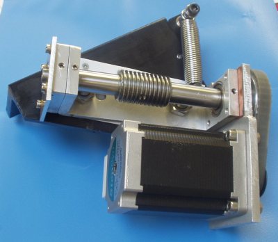
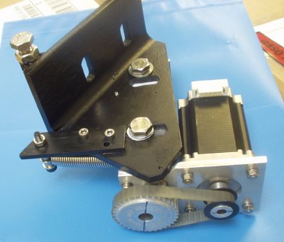
AWR SOLUTION FOR THE HEAVEST TELESCOPES
The Guildford scope has provided the biggest challenge. We needed to cope with a range of telescope load in excess of 2:1 depending on the position of the tube and the fork around the sky. Due to the nature of the beast it was not possible to provide a slipping clutch and so the worm was sprung loaded into the wheel. If the tube comes across an obstruction (it is working in a constricted dome, so this is quite likely) then the motor will wind the worm out of the wheel at a certain torque loading. No damage done and no brackets bent. We needed a 25kg spring to give a force pressing the worm into the wheel of approx 500 Newtons. This is way in excess of the 100 Newtons that we thought would be necessary by calculation. This is explaind by the tube getting very stiff to turn in the fork. The example above is an analysis of the Guiuldford scope and photos of the DEC motor bracket (sprung) are below.
A GEM MOUNT
STEP1: BALANCING THE TUBE
The optical tube assembly (OTA) must be balanced radially. For example a finderscope
will need balancing by adding weight on the opposite side of the tube. If this step
is not done then a different load can be placed on the RA motor if the tube
orientation is changed. This may not affect the performance for small telescopes
but is recommended for all telescopes.
STEP2: CENTRE OF GRAVITY OF OTA
Locate the OTA on the mount. Keeping the DEC shaft horizontal, clamp the RA axis and unclamp the DEC axis.
With the telescope tube horizontal adjust it by moving it in the cradle or
adding weight so that there is an equal force to move the tube in both directions.
STEP3: DEC COUNTERWEIGHT
Arrange the DEC axis horizontal so the telescope
can swing in a vertical plane. Clamp the DEC axis and unclamp the RA axis.
The DEC counterweight must be moved so that there is an equal force to move
the telescope both ways in RA. It must be like this whatever the RA the telescope is
pointing to so try the RA in different orientations with perhaps extra balancing
for a heavy DEC motor.
The DEC motor can be as much as 1.5kg and placed 20cm away from the DEC shaft. It really needs a weight to balance this on the opposite side of the shaft. Without doing this, the counterweight may appear to be needed in different positions depending on the HOUR ANGLE of the telescope.
Finally CHECK the balance in different orientations with both axles unclamped.
A FORK MOUNT
STEP1: As above.
STEP2: BALANCE THE OTA
Unclamp the DEC axis. Adjust the Fork so the tube can point on the meridian. Try the tube in horizontal and vertical attitude. In both positions the tube should stay still. Short focus SCT's are particularly troublesome as it is difficult to see where to put the weight. As a guide there should be balance bars along the top and bottom sides of the OTA along which weights can be slid.
STEP3: CHECK POLAR AXLE
There are no DEC balance arms so there should be nothing else to do. But you need to check that when the telescope points to an hour angle of six hours that there is no balance problem on the polar axle. This shows up as not staying put when at these easterly or westerly pointing positions. Check with the polar axle de-clutched and free to rotate. A problem here could indicate that not all the weights have been balanced - such as a motor assembly which is one one side of the fork only.
Finally CHECK the balance in different orientations with both axles unclamped.
| © 2005-8 AWR Technology | 01304 365918 | www.awrtech.co.uk |
|---|