
|
Worm INDEX PULSE Generation |
After the end of a slew the IH works out where the telescope is in the index cycle and recommences periodic error corrections. Exact synchronism is reached at the next index pulse. The IH display shows if the periodic error corrections are active.
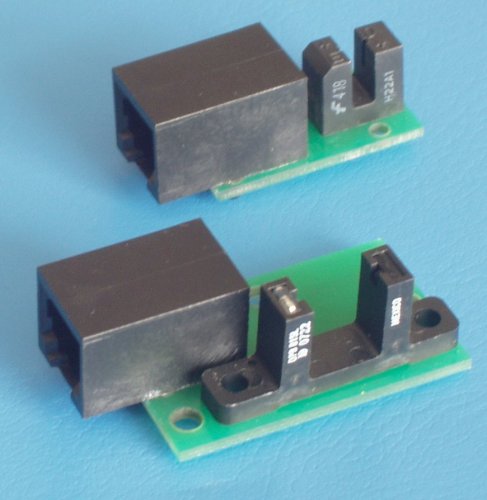
| PRODUCT UPDATE JUNE 2008(right) WITH CONNECTION BOARDS Jaw sizes 3.1mm and 16.7mm TOP HAT and OLD STYLE OPTO_COUPLER (below)
|
|
|---|
Testing of the unit is performed by using a computer connected to the HOST socket in the Intelligent Handset. With the complete system powered up (Drivebox and Intelligent Handset), the IH is put into AWR mode of communications (FACTORY - COMMS). Run a terminal programme such as Hyperterminal. As soon as this programme has been set up correctly the IH will report "HOST CONNECT". You can then rotate the slotted disc and there will be a set of characters reported ":P#". This occurs every time the slot in the disc passes through the opto-coupler. If the telescope is operated at slew speed then the protocol is inhibited as the slot can go too fast through the aperture and there is not enough time to report the pulses. So do the testing at slow speeds.
The electrical circuit looks like:

ALTERNATIVE METHOD OF GENERATION
In many cases with existing equipment it will be very difficult to add the slotted disc as in the above photograph. An alternative method is to have a vane that rotates. This can be attached easily to the rotating component. This must pass through the jaws of the opto coupler at some point in its rotation. The pulse generated becomes the other way up but as the pulse detection is on an edge it does not matter to the electronics which way up it is. So the SAME LEAD can be used.
| Intelligent Handset Home | AWR home page | PRICE LIST |
| © March 2003 AWR Technology | www.awrtech.co.uk |
|---|
