
|
MOTORISING & AUTOMATING A DOME |
The motor is a large geared DC motor and gearbox transferring power via a rubber wheel about 15cm diameter to the dome skirt on the inside. A rotation speed half to one degree per second is required. When the telescope is tracking an object near the zenith, the azimuth of the telescope changes rapidly, and so the dome has to rotate fast enough to maintain the telescope beam within the shutter aperture. The forces involved can be quite large but a 60 Watt motor is about right.
The wheel transferring the power must be pressing on the skirt quite hard in order not to slip so there should be another roller on the outside at this position to stop the dome moving off the track. This arrangement 'pinches' the skirt and so allows sufficient torque to be developed on the driven roller without slipping. A pneumatic tyre is preferred as it will take up any irregularities in the surface it is driving.
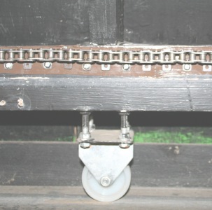
| An alternative transport mechanism could be by a sprocket acting on a chain screwed to the dome to make a circular track. By springing the motor into the side wall any irregularities will be taken up as in these photographs of an actual installation. | 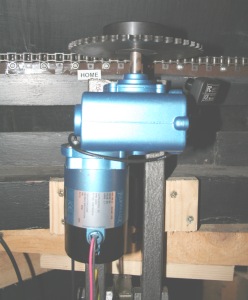 |
 |
Let us work through an example.
A 4 metre diameter dome requires 10Kg force on the edge to start it turning. The force
is measured with a spring balance (such as used by fishermen).
Now 10Kg force is practically 100 Newtons force. If we had a rubber drive wheel (or sprocket) 0.2m
diameter then we need 100 Newtons at 0.1 metre radius or 10Nm (Newton-metre).
The reduction ratio of the drivewheel is 4m / 0.2m which is 20. Therefore 20 revolutions of the small wheel will rotate the dome once. To move the dome at 1 degree per second requires a small wheel speed of 3.33 RPM.
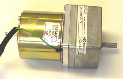
| THE MOTOR
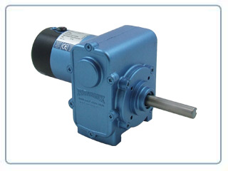
A DC 50V 1.7 amp motor has been chosen to give the most flexibility in control of dome and shutter movements. It can be supplied with various gearboxes giving large output torques. Typical performance is 17Nm output at 3rpm. If a 170mm diameter rubber tyred wheel is fitted to the output shaft of then it will generate 200 Newtons of force. The motor is Parvalux type 50V DC Permanent Magnet PM10 series 60W power rating with double reduction worm gearbox type MIW. DRAWING The gearbox output can be fitted direct to a rubber tyred wheel to drive the dome around or through a bicycle chain geared reduction if more torque is needed. Further information on 'How to measure torques', How to calculate the dome forces'. Talk to Alan Buckman if you need help in assessing how it will work. |
|
| 60W Motor & Gearbox with connecting lead. . . . Ł250.00 |
|---|
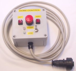
ELECTRONIC PRODUCT 1: DOME ROTATION CONTROL BOX
| Power supply: | Mains 230V 120VA fused at 1 amp | Control Box as described . . . . Ł295.00 | |
|---|---|---|---|
| Output: | Suitable for 50V DC at 2 Amp motor, current limited | ||
| Box: | Wall mounting steel case to IP65 | ||
| Fixed Controls: | LEFT and RIGHT buttons, HOLD IN to operate | ||
| Indicator: | Power ON | ||
| Motor connector: | Quikmate style 4 ways | ||
| Remote control: |
|
The AWR ADVANCED INTELLIGENT DRIVE SYSTEM has relay outputs operated under handset control and this can be used to provide the correct signals for operation of the dome.
SHUTTER CONTROL BOX DESCRIPTION
The shutter control logic works in a different way to the rotation logic and there is additional circuitry in the shutter control box to accept input from magnetic sensors at the extremes of travel The shutter actuates the sensor to stop it moving. The operate buttons are labelled OPEN and CLOSE and are momentary action. A connector takes motor power and sensor switches to the shutter part of the dome. The shutter is opened with the dome in a fixed position and this connector is used to allow the dome to rotate once the shutter has been opened. Once the shutter starts moving there is nothing to stop it and it can be dangerous, so an EMERGENCY STOP button is also supplied that can be fixed up to 3 metres from the control box.
Exactly this control box description was used by AWR on the NPL Solar dome Shutter projects.
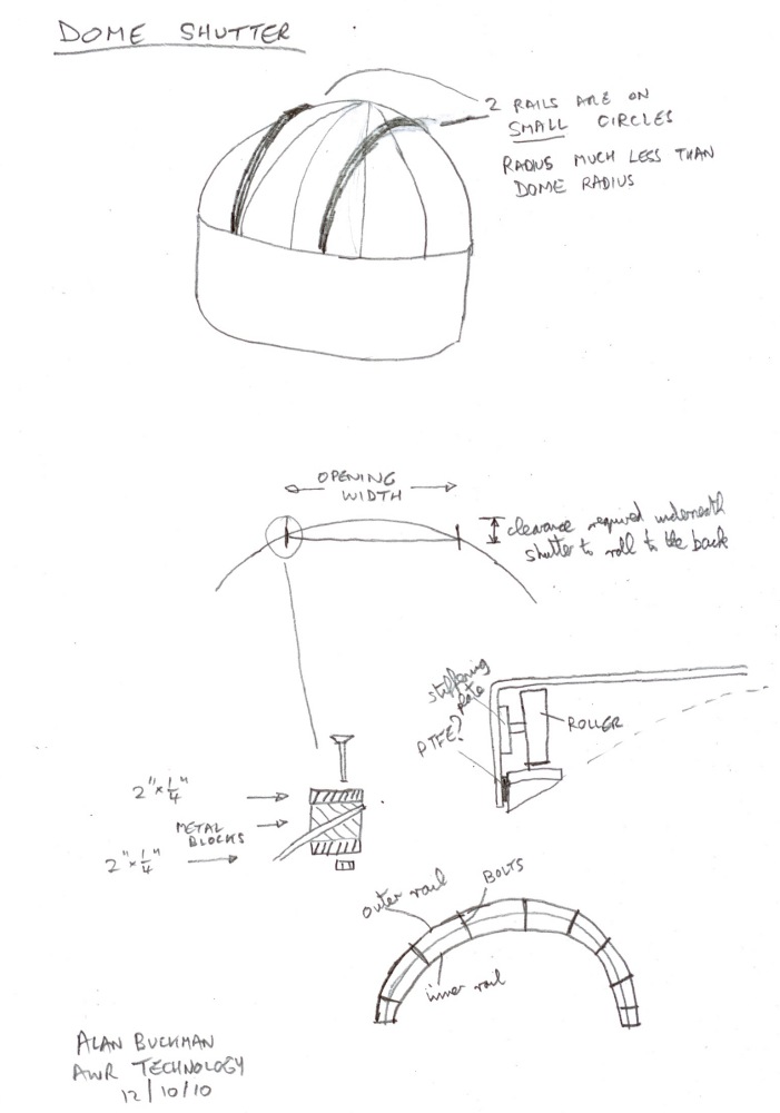
If you need help in deciding how to build an up and over shutter, here are some ideas.
ELECTRONIC PRODUCT 2: SHUTTER CONTROL BOX
The electronics specification is similar to the dome rotation control box.
Shutter control box supplied with sensors . . . Ł375.00
Extra Emergency STOP button, box and wiring . . . Ł40.00
ELECTRONIC PRODUCT 3: COMBINED DOME ROTATION & SHUTTER CONTROL BOX
A combined box to drive either the shutter or the rotating motor from the same current limiting electronics. Only one motor can be operated at once with internal switching to select either the Shutter Motor or the Dome Rotation Motor. It is supplied as a wall mounted box with the controls on a hand paddle (3m lead).
Combined specification.
| Power supply: | Mains 230V 120VA fused at 1 amp | ||
| Output: | Suitable for 12V, 24V or 50V DC motors, current limited to 2 Amp | ||
| Box: | Wall mounting steel case to IP65 | ||
| Dome Motor connector: | Quikmate style 4 ways | ||
| Shutter Motor connector: | Bayonet style 7 ways | ||
| Indicator: | Power ON | ||
| Remote control: |
|
||
| Hand Padle Controls: | DOME LEFT, DOME RIGHT, SHUTTER OPEN, SHUTER CLOSE, EMERGENCY STOP | ||
| Hand Padle Indicators: | Power ON, SHUTTER MOVING / STOP |
|
 |
| Comprehensive Hand Paddle | Shutter Motor assembly 30W motor, 2Nm output at 60rpm . . . Ł200.00 |
|---|
The technique relies on knowing the azimuth of the dome shutter at any instant. By comparing the actual azimuth to the telescope azimuth it is a simple task to command the motor to move the dome to reduce the difference. A low cost method of finding the shutter position is to position magnets at equal distances around the moving part and a fixed sensor to detect. By using several sensors at a different spacing from the dome magnets it is possible to get greater angular resolution on the dome azimuth at the expense of more complex electronics. Resolution is possible down to a few degrees. It is also possible by clever design to get an absolute position of the dome at one azimuth.
The future auto control box will have a calibration feature that allows offset telescopes to be accommodated when the aximuth of the telescope will not match that of the slit, but will still be pointing in the middle of it. A net of calibration points is required for different declination scans and the control box can then interpolate for the best azimuth to keep the slit centred in the telescope beam. It will plug into the REMOTE input of the motor controllers as descrived above. The direction control outputs will be through relays so it will work with any motor control box that has two manually controlled buttons for dome movements.
| AWR HOME PAGE | PRICING |
© 2000-2010 AWR Technology