AWR Logo

Fixing Intelligent Drive System Problems


See also General Calibration issues.
INSTALLATION PROBLEMS - COORDINATES and SPEEDS

These problems show themselves as the following: STUCK DIRECTION - then the direction information from the Drivebox is not reaching the Handset. This could be an open circuit wire in the cable from the Drivebox, or a fault within the Drivebox. This can be confirmed by using the LIGHTS BOX which shows what is happening to the encoder signals (pulse and direction) in RA and DEC. You could try checking continuity in the RJ45 lead by checking between pin 1 to pin 1 etc all down the cable.

WRONG DIRECTION - Change the motor direction sense in FACTORY-USTEP-RA-DIR or FACTORY-USTEP-DEC-DIR. Note it is possible to get the DEC wrong frequently if you assemble the telescope onto the mount at each observing session. It is better to mark the orientation so that you only have to figure it out once.

WRONG DISTANCE - The RATIO must be wrong for this axis. The field is entered in FACTORY-USTEP-RA-RATIO or FACTORY-USTEP-DEC-RATIO. The distance moved should be exactly mirrored by the coordinate change on the IH display. If it is a fixed percentage out then the RATIO is out by the same percentage. You need to do this measurment accurately, preferably with known stars over 60 degrees apart and using a cross hair eyepiece (12mm focal length). Before doing this adjustment you need to be polar aligned as best you can by the DRIFT METHOD. The AWR two star cal method and GOTO's will not work until the RATIO's are correct. This is most likely to be a problem with FRICTION DRIVES only, as worm drives can be precisely calculated.

If the Intelligent Handset is set to KING rate and the RA motor is turning too slowly then it needs to speed up. This means there will be MORE encoder counts for a circle. So the RATIO figure (which is the number of encoder counts in a circle) needs to be BIGGER. This number can be changed without any problems. All speed rates for this axis are re-calculated using the new RATIO.

The CORRECT SITUATION is that the UP button should move the telescope towards the POLE and the DEC coordinate display should go more positive. The RIGHT button should move the telescope towards the WEST and the RA coordinate should decrease. The OPPOSITE direction buttons should have the opposite effects. Also the amount of movement displayed should be the amount the scope physically moves.


VIRTUAL ENCODERS and DIAGNOSTICS

The virtual encoder information is derived from the pulses to the stepper motors. They are generated from every n pulse and not measured. To have feedback from encoders giving 1 pulse per second needs a resolution of 86,400 steps per day. If the motor running is extremely smooth then no pulses are lost and so they can be counted. There are four lines used to send the information to the Intelligent Handset. These supply RA COUNT DIRECTION and CLOCK, DEC COUNT DIRECTION and CLOCK. The direction lines are absolute in relation to the direction the motor turns, that is if the logic level is HIGH on the RA DIR then the motor will always be rotating CLOCKWISE for example. AWR can supply a LIGHTS BOX for the Virtual Encoders which shows the logic levels on these four lines. This can be used in circuit with everything else connected, in series with the lead to the Intelligent Handset (plugs in either at the IH end or the Drivebox end). It can indicate if parts of the Microstep circuit are working and the correct signals are being generated.

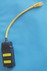
During SETUP of the Intelligent Handset it is possible to get the numbers in the various configuration fields wrong in which case the coordinates appear not to change or go in the wrong direction when direction keys are pressed. The Lights Box can indicate the information flow is correct. When the buttons are used, the direction line and clock pulses should change. The direction line is acting as a count direction (up or count down) on the internal registers kept of the telescope position.

DIAGNOSTICS - If the coordinates displayed on the handset always move in one direction no matter which button you press (UP and then DOWN but the coordinate value always decreases) then the LIGHTS BOX can tell you if the DIRECTION line from the drive box is acting as it should. If it is solidly stuck as ON or OFF when you press either button then there could be a fault in the drivebox or the lead between the drive box and the lights box.


TROUBLESHOOTING SERIAL COMMS

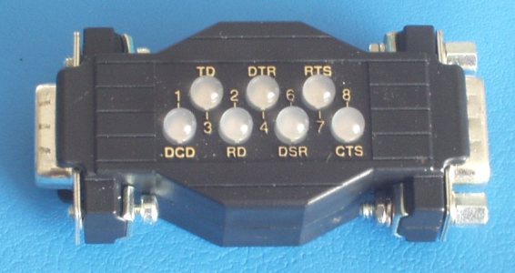
The Intelligent Drive System uses SERIAL RS323 data flow between IH and PC, IH and DRIVEBOX. Constrictions on connector arrangements make special leads a necessity. Both serial ports work at the same protocol (9600,N,8,1) and in addition the IH-PC requires Hardware handshakes using RTS, CTS lines. A very useful gadget is the RS232 SERIAL PORT MONITOR which is self powered and has lights for each of the lines and 9 pin D connectors of the right polarity. We sell these useful devices. So when data flows the lamp flicks colour.
Problems which can be narrowed down are:
  • USTEP TIMEOUT ERROR message
  • No PC Communication
  • Intermittent Intelligent Handset keyboard actions
A useful PC TERMINAL Programme called WINDISP is now available from AWR. See the DOWNLOADS.

PROBLEMS with LAPTOPS:
Certain makes of Laptops with an RS232 9 pin output do not conform to the RS232 standard and only have +/- 5 volt levels, not +/- 10 volt levels. Certain hardware devices will not work at the lower levels. A way round this is to use a USB to SERIAL converter with the correct output characteristics. The one we have tested is in our price list. It has the correct voltage levels and operates 'hardware handshaking' properly unlike some others we tried.

TECHNICAL BITS
GETTING COMMUNICATION:
A common problem in setups is to get serial communications between devices. Here is a checklist and a suggested procedure to find out which bit is not working.
A quick checklist is the following:
Check setup comms parameters, handshaking settings and the right COM port.
Check connecting lead is the correct type. A NULL-MODEM CABLE (LAPLINK CABLE) has two FEMALE sockets on both ends, an EXTENDER cable has a female socket and a male plug.

Finally a check on line activity by an RS232 LIGHTS BOX (a Serial Port Monitor) see photo - or another computer as a terminal. (UK price for RS232 SPM)

1. The setup parameters.
Many serial comms use initial settings which must be the same both ends.
These will commonly be quoted as "9600,N,8,1"
In order these are baud rate (bit speed), parity, number of bits in each data word, number of stop bits.
Speeds can be very slow (110) to very fast (38400) bits per second. There can be 10 or more bits in a character so rule of thumb is to divide the baud rate by 10 to get the characters per second. (This holds for modems over telephone wires as well).
Parity can be None, Odd, Even, Mark or Space and is a type of checksum.
Number of stop bits is the minimum amount of idle required between characters.

2. Handshaking.
This must be matched otherwise characters will not be sent or received. The three possibilities are:-

  • NONE - every byte sent is assumed to be received.
  • HARDWARE or RTS/CTS - hardware handshaking by using additional lines.
  • XON/XOFF - software handshaking obtained by the receiver transmitting a control character to stop and start the sender.

3. The cable.
The connection between the two devices must be by a communication medium which can be wires or infra-red (eg remote control units on VCR's). There must be enough wires to support bi-directional communication if that is required. The minimum will be three wires (Rx, Tx, GND) and two extra for handshakes (RTS, CTS). There may be other wires needed (DTS, DTR) for the handshaking.

A common problem is getting the wrong cable. There are two sorts, one with cross-over connections and the other is a plain extender lead. Unfortunately you can buy both sorts with either two male ends, two female ends or a mix. The correct lead for the Intelligent Handset is a NULL-MODEM also called LAPLINK or PC LINK cable which is intended to connect two computers together via their serial ports.

4. Diagnosis.
It is always possible to use a computer as a terminal to receive and echo characters to the screen. Use Windows HYPERTERMINAL, our WINDISP programme or a DOS programme such as TELIX or BITCOM. These will allow you also to type in characters which are sent down the cable. By this means you can determine if either end is transmitting or responding to characters as they should.

5. The protocol.
This is where everything falls down. The data flow may have to be organised into recognisable packets called a command or a response in order to be intelligable at either end. This is totally up to the programme writer of the equipment being tested. If it is a modem then there are specifications for this stream, called the HAYES protocol which every modem must talk and understand otherwise there would be no communication. The usual structure for messages is to packet them with special starting / ending charcters. Some protocols may require the whole packet to be sent in one go without breaks between the characters. Others will not make sense unless they have calculated CRC's or checksums sent near the end of the packet. There may be a requirement to echo the command sent so that the transmitter knows that it has been heard and understood.

6. The method. To see if characters are coming out and travelling a long a cable all we need to do is listen at the other end with our PC for the first few characters - the start of the first message. If you are in luck the data flow may be recognisable and may convey useful information. Start by setting up the communications parameters to match that of the transmitter. Run the terminal programme and see what happens.

This will also work if you want to see if your terminal programme is sending characters - use another computer at the other end with its own terminal programme. The computers do not have to be PC's. Any computer with an external serial interface can be pressed into service

If there is nothing at all then check - there may be hardware handshakes required. Don't give up. Ther can be broken or shorted wires in the cable. At this point you reach for a multimeter and 1) check for continuity between both ends of the cable 2) check for voltage levels. Rx and Tx idle at 0 to -12 volts. When characters are being sent the voltage will flash up to positive values. RTS and CTS are allowing data flow when they are up at +5V to +12V. Voltage indications can be shown by LED's (usually bi-colour) and a reasonably low cost 'lights box' can be purchased which will diagnose all the commonly used wires in one go.

BUILT IN DIAGNOSTICS
Setting the COMMS mode in the IH to DEBUG allows you to see the data flow between the Drivebox and Handset. Use a serial terminal in a computer to show this. A certain amount of strings used in development of the overall software will also be shown but the basic communication structure is understandable. You need the IH-PC SERIAL lead for this diagnostics.
You can also connect a DRIVE-PC SERIAL lead straight into the drivebox where the Intelligent Handset would normally plug in. This gives you direct control of the drivebox programmable registers and functions as described in the DRIVEBOX PROTOCOL DOCUMENT. The RS232 SPM can be used on this cable at the PC end to see these signals. You can also connect in the LIGHTS BOX to see the encoder information flow.

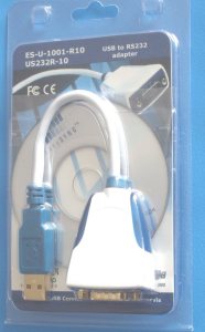
With all these tools it is possible to locate the source of non-working Intelligent Drive Systems. The full list of diagnostic equipment we sell is:

   SERIAL/IH    PC to IH (9 pin 'D' to 6 pin RJ12) converter lead (2 mtr)
   SERIAL/DR    PC to Drivebox serial lead converter 2 metre
   USB/RS232    USB serial converter. The AWR recommended one
   LIGHTS       Lights Box to show VIRTUAL ENCODER information flow
   RS232 SPM    Serial Port Monitor 9 pin D leads


WOBBLES IN RA FOLLOWING

There can be many causes of the RA drive not being smooth at the arc second level as outlined below. In many cases the modern autoguiders can correct for most of these errors, provided there are no large amplitude jumps happening over a short timeframe. If any readers / users have experience of any of these errors or any other errors then please submit to AWR and we will add to the knowledge base.

Firstly, a method of detecting and measuring wobble is to take a photograph at prime focus of the telescope when there is a small DEC drift. The exposure should be about 10 minutes and the DEC drift should be about 10 to 20 arc minutes over this time. With the Intelligent Handset it is possible to put it into TRACK mode with a DEC drift parameter settable by the user. Make this 1 or 2 arc second per second and then you will have the correct size of DEC drift. Alternatively if you mis-align the pole you will get DEC drift. You will have to measure the photograph, or digitise it and send it to me along with some information - focal plane scale (or focal length), duration of exposure and the DEC track rate.
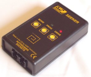
An alternative method for measuring all sorts of drive errors is to use the AWR SEEKER.

CCD cameras can also help in gathering data. Using ASTROART it is possible to get a readout of the error every 0.5 second and so it is easy to build up an array of data covering at least two cycles of the longest component (the worm revoltuion period). Then the data can be analysed in a programme like DPLOT to get the RMS error and all the periods using FFT analysis. This is a very powerful technique which uses all the data to dig out any signals from the noise.

Actual example of periodic error with FFT ANALYSIS and further discussion.

It is possible to get multiple periods of the main worm as the overall periodic error period if there is a gearbox involved and the ratios are not harmonically linked. Thus the Meade LX200 drive has an overall period of THREE cycles of the worm wheel. You would think that it would not affect it much but the gearbox is not that good with large errors in each axle. The Alter D6 has harmnically linked periods in the gearbox components so one cycle is sufficient to get ALL the periodic error, shown in the FFT analysis.

SHORT TIMESCALES - REGULAR PERIOD of 64 MICROSTEPS
This corresponds to an error in the microstep translation sequence. The deficiency is a regular lowering of torque during a complete step cycle. The size of the wobble will depend on the torque required from the motor and its period will be about 3 seconds with 144 teeth reduction or 1 second with 360 teeth reduction. The wobble amplitude can be reduced in size by increasing the reduction ratio (not easy unless you add gears) and hence reducing the torque requirement. It can be eliminated by a software upgrade to replace the microstep translation tables with version B tables. The downside of Issue B is a reduction in torque available for high speed slew.

Issue A translation tables also have a varying current requirement from the power supply. The larger MOTOR/120 motors require 4 amps to 6.5 amps in a 64 microstep period. If there is a long power lead to the power source, or thin cable has been used then the extra volt drop at the larger current will cause an unnecessary reduction in torque available. This can also happen if the power source is not capable of supplying the 6.5 amps when voltage droops will occur. It will be possible to determine this by measuring the voltage at the drive box over a short period. There will be a wobble in the steady voltage. It it varied from 12.0 to below 11.5 then it would indicate a problem.

REGULAR PERIOD of 1/4 THE WORM PERIOD
If there are exactly 4 wobbles per revolution of the worm then there is a definite cause! There must be an OLDHAM COUPLING connecting the motor to the worm shaft and the two shafts are not aligned well enough. With misalignment you get a period exactly 1/4 the full revolution. This error can be modified by attending to the OLDHAM COUPLING or by using periodic error correction. It has a fixed phase relative to the full rotation so can be taken out with the worm periodic error correction. Other sources of multiple cycles exactly within 1 rotation of the worm period can be due to others gears or shaft working at higher speeds. Try another design of shaft coupler - there are several on the market.

LONG TIMESCALES - REGULAR PERIOD OF ONE WORM REVOLUTION
This is most likely to do with periodic error in the worm wheel. On the trail photograph this will show up as a regular wave on the photograph. A 144:1 worm has a period of 10 minutes, 287:1 is 5 minutes and 360:1 is 4 minutes. This is one of the reasons why the initial exposure should be quite long in duration.

It can be removed mostly by doing a careful periodic error correction procedure. The training may not remove all the error, because it may not be completely periodic or the training was not exact. A programme such as PEMPro can help to produce a much smoother periodic error table.

If there is a deep departure from a sine wave at a particular point on the worm rotation probably due to a shaft binding, where a lot of extra torque is required to turn the shaft. Closer examination by stripping down would be called for. It could be the worm not running true, or bearings have become worn.

Once you know that the wobbles are periodic then it is possible to do something about it. ASTROART can record the periodic error trace and then play it out to the AWR Intelligent Handset or Meade LX200 type equipment or Vixen SS2K drives. It is further possible to build in an INDEX pulse coming from the drive train so that the periodic error trace can start at exactly the same point on each revolution. The AWR equipment can use an INDEX pulse.

IRREGULAR WOBBLE
If the drive is lagging then suddenly catches up and this repeats at an irregular period there may be several problems in the drive train. There could be stiction in the main RA telescope drive shaft due to very large weights. In this case it will require a lot of torque to get it moving and then it gives suddenly but it could stick again. A 16" Newtonian with an optical tube assembly of 100kg can exert considerable forces at the bearings and gears. Look for mis-shapen gear tooth or bent shafts as a cause. The metal work supporting some of the drive components may be distorting at certain torque values causing the jumping. Worm alignment may be another cause for an irregular wobble.

If you undo the worm, allowing the axle to rotate you may be able to feel the problem by a variation in the torque required to turn the axis. Look for roller bearings with tight spots. This can be caused by end float adjustment being too tight and causing uneven wear in the bearing - roller bearings are not designed to have axial forces, you need thrust bearings. Manufacturers still get it wrong.

Solutions involve re-aligning or re-greasing bearings, adding roller or taper bearings, adding thrust washers or adding extra locations for grub screws, stiffening metal work etc.

If you are autoguiding and you get an irregular jump in the RA direction then this could be due to BACKLASH if you are operating the motor at more than 2x sidereal rate for the corrections. At this adjust rate the RA motor is actually turning backwards. This is avoidable and the solution is to lower the adjust speed when the direction buttons are pressed by the autoguider. (See also DRIVEBOX JUMPER setting for GUIDE speed on the AWR Microstep system).


REDUCING VIBRATION PROBLEMS

Stepper motors inherently move the telescope round in small discrete steps and this can induce vibration. An overly powerful motor can ring at a step and transfer more vibration to the telescope. However, when the motor pulls the telescope round it is exerting the same torque on the telescope mounting which must not flex, else the mount itself can vibrate. We have to take care of the torque on both sides of the motor to reduce vibration. Note it cannot be eliminated, it can just be reduced until it is not perceptible. We are also just discussing the RA motor.

VIBRATION - THE MOUNT
The mount must be rigid. The RA motor is in a fixed position so this it is essentially an easy job to make the mount rigid. A tripod does have problems but extra strengthening struts can be fitted. Also a vertical rod can be fixed to the equatorial head, hanging down to between the legs and fixed at the accessory tray level. A pier mount if permanently fixed is easy to deal with - fill it with sand for dampening, or with concrete to make it rigid. The diameter of the pier can also be increased, definitely necessary if it needs to be higher than one metre. Eight inch diameter is recommended.

THE WORMS
If the worm sets are fresh they can transmit and magnify vibration as well as have a large periodic error. After "bedding in" the worms can settle down especially if greased. To speed up the bedding process it is possible to use "lapping oil" and run the drives at high speed for long periods to even out the high spots on the worms and wheels.

OVERLY POWERFUL MOTORS
This can be caused by small motors with a large gearbox (our STEP3 motors) when the telescope inertial load is not matched to the motor at the motor shaft. Try adding friction on the worm shaft to stop the gearbox ringing. This can be done with with an extra collar around the worm shaft with a grub screw and a PTFE blob against the shaft.

ELECTRONIC METHODS
If a gearbox is attached to the motor then it is possible to change the gear reduction ratio and hence drive the motor with more steps per second. This reduces the step size in the sky but may not reduce the ringing problems. Other electronic methods include half stepping instead of full stepping or of soft start on each coil when energised. All of these require hardware modifications and so should be done as a last resort. Changing the motor step rate will also affect the high speed slew achievable.

Any other suggexstions that you have found to work please e-mail me and I will add it to this page.


DRIVEBOX JUMPER SETTING
Inside the Microstep Drivebox is a jumper setting which sets the default speed when the SIMPLE handset or the Autoguider inputs CCD1 or CCD2 are used.
This shows the jumper (JP1) setting to OPEN.
The default guide speed will be set to the CENTRE rate.
CENTRE = 2.5x sidereal (default)

Changing the link to cover both pins changes
the default guide speed set to the GUIDE rate.
GUIDE = 30% sidereal (default)

(See also AUTOGUIDING page)

Note that the Intelligent Drive System can operate with TWO handsets connected at once (the IH and the SIMPLE handset). The speed for that handset is taken as the speed setting on that handset. The autoguider inputs take the speed of the SIMPLE handset speed setting. If this is not present then the JUMPER limk sets the default speed as shown above. The IH can change the default settings.

If the SIMPLE HANDSET is being used then the jumper (JP1) must be set to OPEN else all the speed settings will not be available.

Early versions of the MICROSTEP DRIVEBOX did not have a jumper on the pcb and so the default speed from the simple or the CCD connector is the IH CENTRE rate. So to avoid any jumps with autoguider use, lower this setting to about 1.70 from the default of 2.50


Intelligent Handset Home AWR home page PRICE LIST email AWR

© 2005-8 AWR Technology