
Guidance for IDS Owners
www.awrtech.co.uk
|
Guidance for IDS Ownerswww.awrtech.co.uk |
|---|
| LATEST VERSIONS | |||
|---|---|---|---|
| IDS HANDBOOK | V1.4 | download | |
| INTELLIGENT HANDSET | V1.730 | history | |
| IH DATABASE | DB 01 | details | |
| DRIVE BOX - ALL VERSIONS | V0.74 | history | |
| MICROSTEP TRANSLATION TABLE | 1 phase - 2 phase drive for max power |
4042 | notes |
| MICROSTEP TRANSLATION TABLE | 1 phase (wave) drive for max tracking accuracy |
4042Bv7 | notes |
| INDEX TO TOPICS | |
|---|---|
|
|
| Have you any suggestions to make? Please send an e-mail to Alan Buckman. |
|
It is safe at all times to plug / unplug the IH at any time when the drive box is powered. If power is applied when the whole system is connected, on some systems the IH may not power up properly due to a slow power edge rise time, and you will only see a lit display but no operation. It is not advisable to disconnect motors whilst they are powered as a large voltage can be generated at the motor pins, but no damage will result.
Do read the sections on hints and tips about the Handbook and look at the QUICK SETUP CHECKLIST in Chapter 8 in the User Manual.
If you are making motor brackets do make sure the metal sections you use are substantial (5mm or thicker) in order that they do not bend when the motors are fitted and operational. Considerable forces build up and the motors must be held rigid. The transmission of power through Oldham Couplings should also be along a single axis if you can adjust it to be so. If there is some mis-alignment through the coupling then there may be a small periodic error introduced at 1/4 of the revolution time of the shaft.
Further information of a general nature is given here. This is a copy of the Installation Instructions sent out with every drive system. Continue installation by reading the paragraphs on MOTOR POWER, BALANCE, MREV setup, POLAR ALIGNMENT. If faults develop then have a go at diagnosis - we have some TEST ACCESSORIES that may help.
Here are some tips that may help you. More are given in single sheets you can download from our downloads page.
At power up in the NORMAL screen select F4 (=SLEW) and check the telescope directions are correct. the four buttons in the middle in the diamond shape are the DIRECTION buttons. Orient the telescope about 0 degrees DEC pointing southerly (when the telescope is in the Northern Hemisphere) or northerly (Southern Hemisphere). Pressing the UP ARROW button should move the telescope UPWARDS towards your local pole and the DEC coordinate displayed should also adjust correctly. If neither of these then alter the DEC SENSE. Similarly for the RA press the RIGHT ARROW BUTTON and the telescope should move to decreasing RA value and round to the WEST when in the Northern hemisphere. If not then alter the RA SENSE.
When GOTO's are used, the telescope immediately starts by itself when the coordinate is entered and the 'E' (ENTER) button is pressed. Pressing a direction button will cancel the GOTO.
The drive system is optimised by AWR Technology at design stage to provide adequate power to slew the telescope at least 0.5 degrees per second which is needed for GOTO operation. However on some systems the mechanical performance needs to be tweaked to achieve this. Seek advice from AWR if your system seems underpowered. The motors do run HOT - this is NORMAL. They must be energised even when stationary to maintain a microstep position.
TRANSLATION TABLE
There are two versions of microstep translation table.4042 provides the most
power at the expense of introducing a small periodic wobble (arc seconds). It
is "two-phase" drive at high speed (half stepping) and has a period of 64 microsteps. The motor
drive current is not constant hence the torque obtained is not constant. 4042Bv7
translation table offers a nearly constant torque throughout the microstep
cycle but offers about 40% less torque. This means it has less power at high
speeds so the slew speed will be lower. This can be compensated by more phase current.
MOTOR CURRENT
It is possible to increase the phase current to the motor in some installations
by about 10% (and hence 10% more torque) by changing the phase resistors or the
drive voltage. The
overall current requirement will be higher so make sure the power supply can
deliver this. This increase may not need hardware modifications.
DRIVE VOLTAGE
By increasing the system voltage to 24V (also needs modified hardware) we get
the motor current into the winding that much quicker, so it is there for
longer for the same step length. Hence more power at higher speed. AWR do a
range of product to operate at 24V based around a power supply of 8.4 amps at
this voltage including a resistor dropper box which is fan assisted to get rid
of the heat.
OTHER IMPROVEMENTS
Finally the telescope can be tackled to reduce friction which can appear in the
drive train. Check the mash of the worm - it may be done up very tight - but
lapping the worm gear can help. Finally an extra gear reduction stage can be
introduced as an extreme measure. Swapping over the MOTOR/120 for MOTOR/210
can also be done without changing the dropper resistors as the phase currents
for these are very close. This can achieve an extra 40% power.
|
DISPLAY UNITS. Model AD100 with large red digits to display any selected parameter of RA DEC ALT AZ HA LST UT. It fits in line on the serial port and can be daisy-chained.
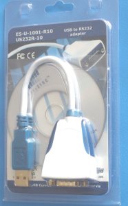
SERIAL CABLE. A lead which plugs into the IH HOST connector to a computer 9 pin serial socket. Normal length supplied 2 metres. USB - SERIAL. Converter for use with USB outputs on computers. We have tried several makes but only this one works properly. This one is designed by FTDI. Picture on the right. IH BASE STATION. A docking cradle that the IH fits into to allow using on a desk. It comes with a small plug top power supply to power up the IH away from the telescope and a serial lead to plug into the computer. The power supply keeps the OVEN at the correct temperature to keep the crystal going at the calibrated rate for highest clock accuracy.PICTURE |
 |
EXTENDED LEADS. We can supply RJ45 Cat 5 patch cords up to 10 metres in length to operate the IH away from the telescope.
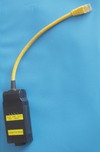
LIGHTS BOX TEST EQUIPMENT. A small adapter that plugs into the Drive Box to show you the state of the Virtual Encoder lines, clock and direction, from RA and DEC axes. picture
INDEX HARDWARE. Pulse generating component to fit on the worm axis (RA slow motion axle). HERE
CCD AUTOGUIDER SIMULATOR. A box to plug into standard 6 pin input sockets showing the state of the lines with manual direction presses.
The SEEKER For diagnosis of drive performance by a device that plugs into the CCD autoguider input. Also used for creating panoramas and spiralling to find objects.
| FACTORY PROGRAMMING | ||
|---|---|---|
| ITEM | LOCATION | TYPICAL |
| Drive box frequency | FACTORY - USTEP - XTAL | 4915200 |
| Drive box RA microsteps | FACTORY - USTEP - RA - MSTEP | 64 |
| Drive box RA ratio | FACTORY - USTEP - RA - RATIO | 720000 |
| Drive box DEC microsteps | FACTORY - USTEP - DEC - MSTEP | 64 |
| Drive box DEC ratio | FACTORY - USTEP - DEC - RATIO | 288000 |
There are in addition other items to programme in the FACTORY MENU. If the telescope is on a German Equatorial Mount, or any other that needs tube reversal at the Meridian then the item MREV in the RA menu should be set to YES. The acceleration and max slew rate are also set in the RA and DEC menues. As a guide heavy telescopes may get up to about a degree per second but light ones can be programmed up to 5 degrees per second slew. The number to put in for acceleration can be entered by trial and error to see what it does. Microstep systems will slew up to 25000 steps per second or thereabouts. To accelerate over 4 seconds would need an increase of 6000 per second or 600 per 0.1 sec so we enter 600. FRGEN units slew up to a quarter of this.
A SHORTFORM of the Factory Menu Tree to laminate.
A full circle contains all or most of the following items:
Multiply all these factors together for the total number of microsteps per circle and
programme in two numbers: MSTEPS = 'y' and RATIO = TOTAL NUMBER / 'y'
If you have a friction drive then some adjustment in the value may be needed - see LINK
The FRGEN unit is more complicated in that the MSTEP number is electronically derived
and there is an extra factor of 2. It may also half step the motor when 'y' is 2 but
the MSTEP number to be programmed is 16.
Examples:
| TELESCOPE | WORM RATIO | GEARBOX RATIO | MOTOR STEP PER REV | DRIVEBOX | MSTEP | RATIO |
|---|---|---|---|---|---|---|
| ALTER D6 | RA: 200 | 56 | 200 | FRGEN | 16 | 560000 |
| Beaconhill Fork 14" worm | RA,DEC: 360 | 1 | 200 | USTEP | 64 | 72000 |
| EQ5 KIT | RA,DEC: 144 | 58/16 | 200 | USTEP | 64 | 104400 |
| VIXEN SP GP DX | RA,DEC: 144 | 120 | 48 | FRGEN | 16 |
It was decided to split out the processing at an early stage between driving the motors and the intelligence required to provide GOTO's. Thus the drive box concentrates on driving the motors smoothly in both axes accepting step rates of approx 1 microstep in 20 seconds to 50,000 microsteps per second and smooth acceleration between all step rates. Driving the motors turned out to be very complex with 4k words in a PIC. However, it is fully programmable and has its own protocol for connection to computers if required.
The handset turned out to be a time consuming monster. It currently has 63k of code on a high performance 8051 (a DALLAS part) and is complex, but it has a lot to do. All the hardware and software (for all parts of the IDS) has been developed by ourselves so we can implement new features as and when time permits. Note space is very short for adding new features.
Calibration of the complete circle by measurment (a traditional two star calibration) was not on for the accuracy we were aiming at. Indeed knowing all the reduction ratio's it was felt better to enter the number directly to ensure the exact rates. It does mean that there may be some experimentation with friction drive ratio's but it is easy to do. Similarly, polar axis mis-alignment requires the DEC to drive very slowly and this was felt to be a bad thing. Image rotation results and it complicates the calculations for positions. So the two star calibration software presented here tells you how far out the pole is, inviting you to correct the alignment before proceeding. This is a once off operation for observatory mounted users and can be done precisely, then you only have to drive in one axis to track properly. It is not that difficult to do even for portable scopes and may take 10 minutes at the start of the session.
Effort was concentrated on making a Planetarium connection possible so that there would be access to the many thousands of objects stored in their catalogues, thus relieving the IH development of a major task for the time being.
I hope you like it. There are many satisfied owners, many of whom could not have achieved GOTO systems at all without this kit.
Alan Buckman, AWR Technology
© 1998 - 2008 AWR Technology